Builder Foundations
Learn the essentials of combat robotics.
Before you build, it helps to understand the parts and principles that make robots work. This section covers safety guidelines, component basics, and how to choose and use motors, batteries, ESCs, and other key parts. Whether you’re brand new or refining your build knowledge, these guides help you build smarter and safer.
Safety
Turnabots are among the safest combat robot kits available. HOWEVER, there are still several things to be aware of if you are building any combat robots:
Lithium Polymer (LiPo) batteries are powerful but must be handled carefully.
Always charge LiPo batteries in a LiPo safety bag or far away from anything flammable.
Never cut both battery wires at the same time. If you need to change a connector, cut one wire, attach it to the new connector, then cut and attach the second wire.
If a LiPo battery is damaged or swollen (“puffed”), do NOT charge it. Dispose of it safely according to proper battery disposal guidelines.
Avoid over-discharging LiPo batteries. Running a LiPo too low can permanently damage it.
- Assume all electronic joints and components may contain exposed lead.
Do not lick electronics. Do not allow children or pets to lick or mouth electronic parts.
After handling electronics:
Do not touch your face
Wash hands with soap and cold water, especially before eating.
Components
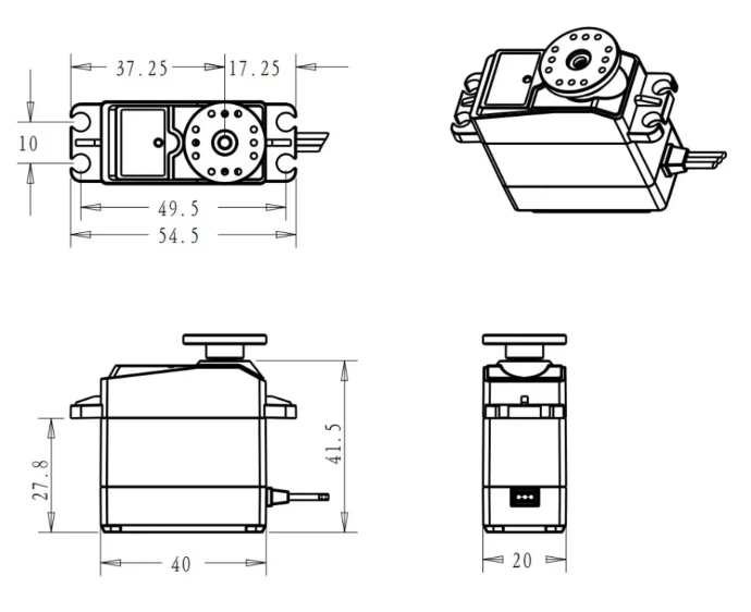
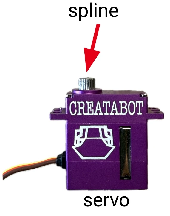
A servo (short for servo motor) is a small motor, gearbox, and sensor that can rotate the spline (the small gear shaft sticking out of the servo) to a specific position and hold it there. With the servo horn on the spline it becomes a mechanical arm that turns a set amount — not spinning all the way around like a regular motor.
Micro Servos
The 3 primary Turnabot micro servos all identical in size and mounting pattern — each is optimized for a different performance priority: speed, torque, or safety.
1. KST DS215MG - SPEED - This is our primary servo. It's the fastest battle-worthy (can get very hot) servo that is reasonably priced.
2. KingMax KM1203MD - TORQUE - These have substantially more torque and are just a smidge slower than the KST.
3. Creatabot Purple Servo - SAFETY - These are more classroom friendly servos with nearly the performance of the KST but after stalling for more than a few seconds they "sleep" until the next signal. "Spamming" the stick can still make them hot, they just tend to run cooler when abused.
Full size servos
The Turnabot DS3339SSG is the absolute fastest full-size servo we could develop at an accessible price point.
Specialty servos
The KingMax C507 is a "slim-wing" servo where minimum weight, speed, and reliability exceed torque requirements.
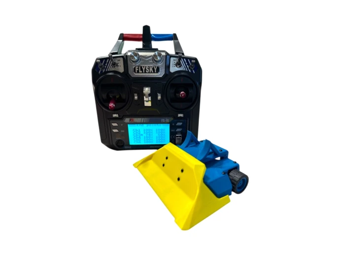
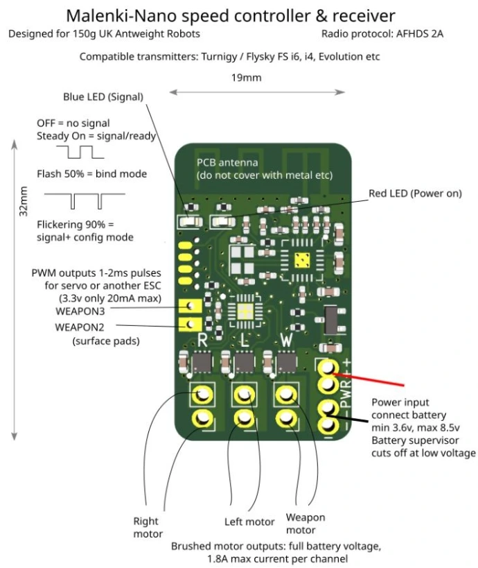
Receives signals from your radio (like the FlySky FS-i6)
Drives two motors — one for the left side, one for the right side (this is how your robot moves!)
Can control a third brushed motor for a weapon
Supports two Pulse Width Modulation (PWM) outputs - PWM can be used to drive servos and / or brushless motor Electronic Speed Controllers (ESCs)
✏️What’s PWM? PWM stands for Pulse Width Modulation — a way of turning power on and off very fast to control speed or position.
Think of PWM like flicking a light switch really fast — longer “on” time = more power!
PWM tells ESCs how fast to go and in which direction.
It also tells servos how fast and how far to turn.
What’s an ESC? An ESC (Electronic Speed Controller) tells a motor how fast and which direction to spin. It gets signals from the receiver chip on the Malenki and powers your motors — like a remote-controlled gas pedal!
Accepts battery voltage between 3.6V and 12.0V
A LiPo, or lithium-polymer battery, is a lightweight, high-power battery commonly used in robotics, drones, and RC vehicles. When you see a battery labeled 2S, that means it has two cells connected in series. Each cell provides about 3.7 volts, so together they make 7.4 volts when set for storage and 8.4 volts when fully charged.
The voltage tells you how much electrical “push” the battery provides—higher voltage means your motors can spin faster and deliver more power. But LiPos need careful handling: never puncture, crush, short-circuit, or drain them too low. Running a LiPo below 7.4 volts can permanently damage it.
Compact and surprisingly strong, LiPos deliver big bursts of current that make combat robots fast, responsive, and full of energy—when used safely.
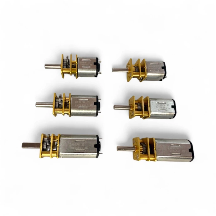
Brushed motors use internal brushes to transfer power to the spinning part of the motor. They are easy to use, inexpensive, and commonly used in small robots because they work directly with basic motor controllers. In Turnabot kits they are used to drive the wheels.
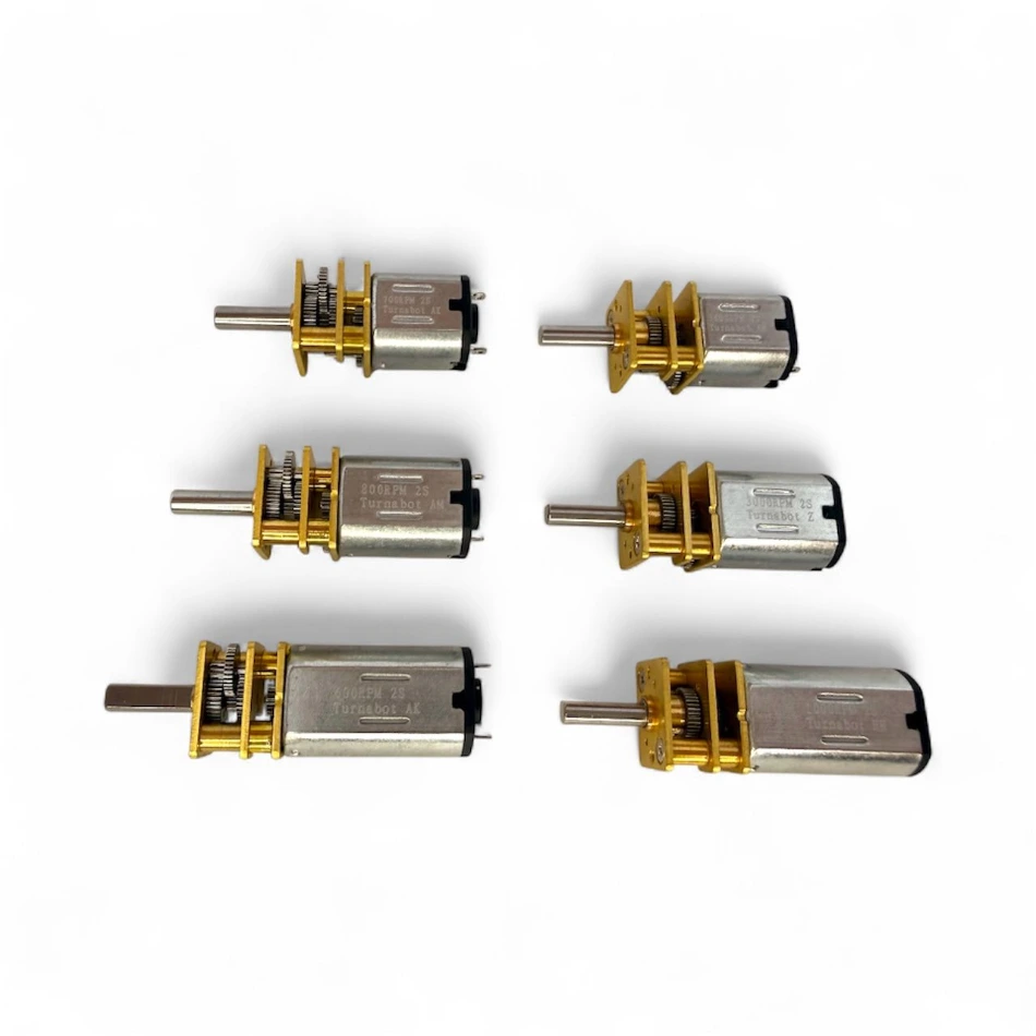
These motors are available with spur gearboxes and planetary gearboxes.
Spur gearbox motors
Standard Turnabot kits come with N10 1650 rpm motors, which are small, lightweight, and quick.
SCAR and SLCR kits use the larger N20 1400 rpm motors, which have more torque (turning power) for tougher matches and heavier robots.
The letters and numbers (like N10, N20, and N30) describe the size of the motor housing—an N10 is smaller than an N20, which is smaller than an N30. Bigger motors have more power and create more torque, but they also add weight.
The speed rating, shown in rpm (revolutions per minute), tells how fast the motor shaft spins. A higher number, like 3600 rpm, means more speed but less torque. A lower number, like 1200 rpm, gives slower motion but stronger pushing power. Choosing the right motor depends on what your robot needs most—speed, strength, or a balance of both.
Planetary gearbox motors
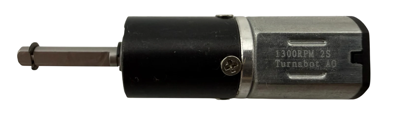
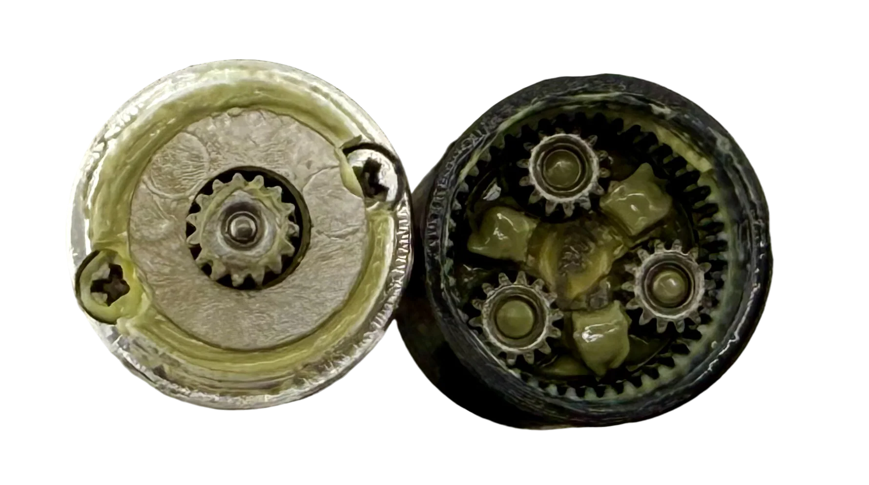
Planetary gearboxes distribute shock loads through the carrier and ring gear, significantly reducing shaft bending and tooth shear that commonly disable spur gearboxes during impacts. Multiple planet gears share the load, allowing far more torque to be transmitted within the same 12 mm diameter envelope.
Each Planetary 12 features a 16 mm output shaft with a machined retention notch and ships with an included circlip (compatible with other retention hardware). This provides dramatically improved wheel retention under weapon hits and wall impacts.
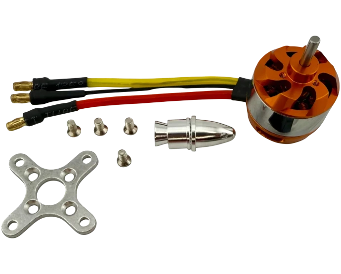
Brushless motors are electric motors that use electronic controllers instead of brushes to spin the motor. They are typically more efficient, more powerful, and longer lasting than brushed motors, but require a special controller called a brushless ESC to operate. In the Turnabot kits they can be used to drive weapons.
These motors are often used without gearboxes but are also available with planetary gearboxes.
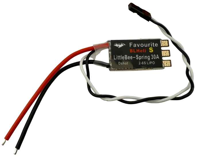
Brushless Electronic Speed Controller (BLESC)
Because of their performance advantages, brushless motors are widely used for high-power drive systems and spinning weapons, but brushed motors are still a great choice for simple, reliable robots and beginner builds.
The switch on your Turnabot has three metal prongs, or terminals, coming out of the bottom. It’s called a Single Pole Double Throw (SPDT) switch. That means the center prong can connect to either of the two side prongs — but never both at the same time.
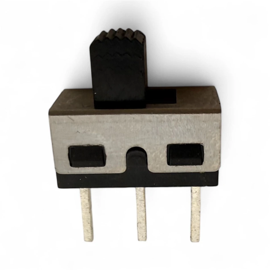
Here’s how it works:
The battery wire connects to one side prong.
The Malenki (the robot’s control board) connects to the center prong.
When you flip the switch on, the center prong connects to the battery prong, sending power to the Malenki and turning the robot on.
When you flip the switch off, the center prong connects to the other side prong, which isn’t connected to anything — so power is cut off and the robot shuts down.
This setup ensures that when the switch is off, both the battery and the control board remain safely disconnected.
These small switches are tough, lightweight, and make it easy to control power without unplugging your battery every time.
Your Turnabot uses stranded copper wires coated with colored insulation. The insulation protects the metal inside and makes it easy to tell wires apart — for example, red for positive and black for negative. These flexible wires carry power from the battery to the motors, switch, and other components.
When preparing wires, builders typically strip and twist the ends to expose clean copper, flux and tin them to improve conductivity and reduce heat stress, and finally solder them in place to create strong, reliable electrical connections.
Taking the time to cut, strip, twist, flux, tin, and solder carefully keeps your wiring organized, strong, and reliable.
- Screws and fasteners to hold everything together.
- Self-tapping screws have pointy tips and more aggressive threads to let them screw in securely to undersize holes, or even no holes at all.
- Machine Threads are used for precise fitting holes and when connection is needed all the way to the end of the screw.
- Washers spread the load of the screws making stronger joints and allowing easier motion where required.
- Hex drivers are similar to "Allen Keys" and drive screws with hex holes. These are used in most places in these bots
- Phillips drivers are screwdrivers with across-shaped tips that fit into screws with a matching “+” slot so you can easily tighten or loosen them without the tool slipping, such as the servo horn mounting screw.
- Aluminum rods are used for lightweight and robust pivots.
- Paper clips are used as pivots and to make tools to pull rubber bands through small gaps.
- Blu-Tak can be used to hold parts and wires for soldering.
Connectors make it easy to attach and remove parts of your Turnabot without soldering everything directly together. Each type of connector has a specific job and color pattern to help you plug things in the right way.
Servo Connector:
This 3-wire plug connects your servo (the part that moves your weapon) to the control board.
- Yellow = Signal (tells the servo what to do)
- Red = Power (gives it energy)
- Brown = Ground (completes the circuit)
Always match the colors correctly when you plug it in — flipping it backward can stop the servo from working.

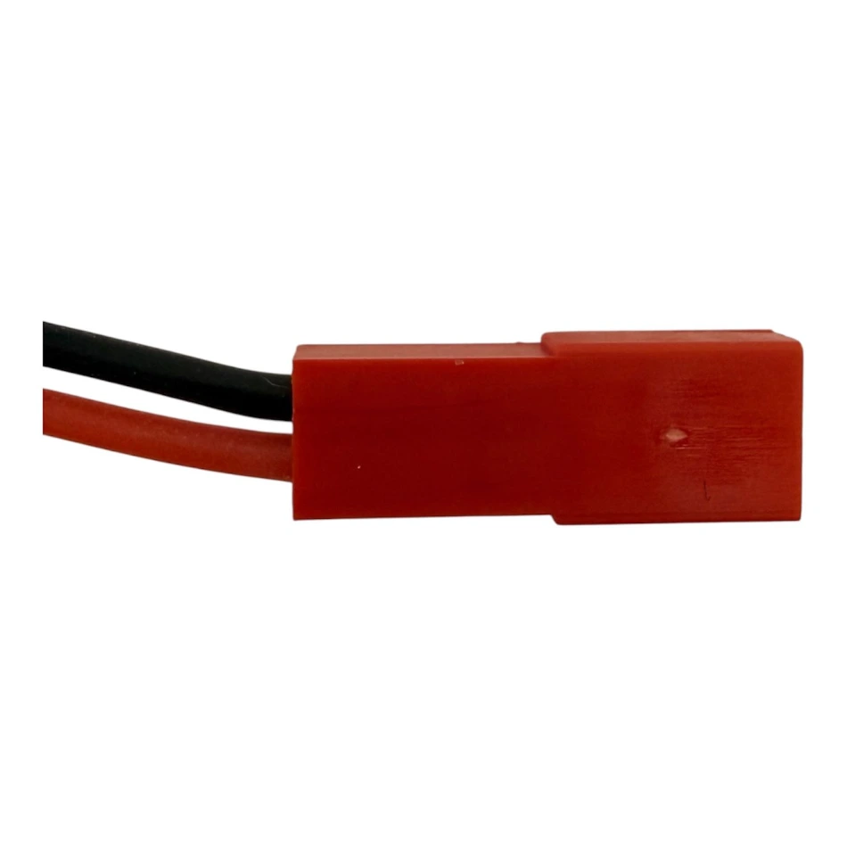
Battery Connector (JST):
The red JST plug connects the LiPo battery to the power harness.
- Red = Positive (+)
- Black = Negative (–)
Plugging this in backward can damage your electronics, so double-check the color match every time.
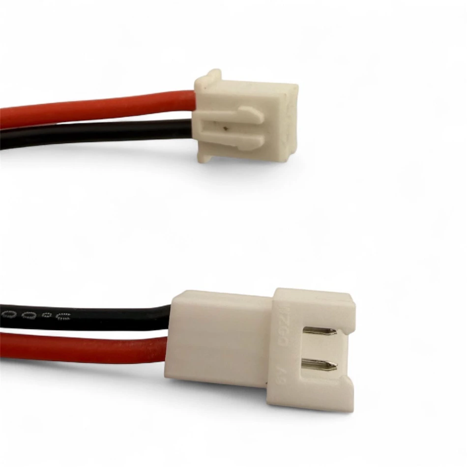
Motor Connectors:
Each motor wire has a small plug at one end and a longer matching plug at the other.
- The small end connects to the motor.
- The longer end connects to the Malenki control board. This makes it easy to swap motors or make repairs without resoldering.
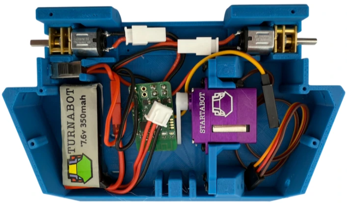
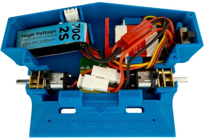
The harness is everything that is soldered together:
Keeping the final design in mind will help you make effective decisions throughout the building process, ensuring a cohesive and functional end product.
Harness Installed in Creatabot
Harness Installed in OverThrow
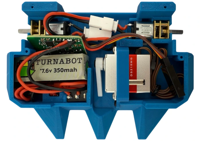
Harness Installed in Squeezy
Build Lab
Practical guides to help you design, build, and improve your robot.
This section is where the real building happens. Learn how to wire components, set up radios, connect brushless systems, troubleshoot common problems, and design better robots. You’ll also find tips for 3D printing, soldering, tool selection, and avoiding common mistakes.
Typical Mistakes: Start Here!
Before you begin the design and building of your bot, check out the following common mistakes that you want to avoid!
- Make sure your bot can self-right, which means that it should always be able to get back to it's wheels.
- Make sure there is no position, such as on a flat side, that your bot can get stuck on.
- When you are designing a bot from scratch, leave room for components, wires, connectors, and room to insert tools for repairs.
- Leave time for testing, modifying, practicing, and producing spares.
Tools
Building combat robots is easier—and a lot more fun—when you have the right tools. This section highlights common tools builders use for assembling, soldering, repairing, and modifying their robots, along with recommendations for tools that are helpful to have versus tools that are simply nice to add as your workshop grows.
Choosing Screwdrivers for Small Combat Robots
The right screwdriver makes building and maintaining your robot much easier. Small combat robots use a wide variety of fasteners, and using the correct driver helps prevent stripped screws and damaged components.
Use the correct size and type.
Many small robot kits use hex (Allen), Phillips, or Torx screws. Always match the driver size exactly to the screw head. A driver that is slightly too small will slip and strip the screw, making it difficult to remove later.
Precision drivers are essential.
Small combat robots often use tiny fasteners such as M2–M4 screws, so a precision screwdriver set designed for electronics or hobby work is very useful. These sets typically include a range of small bits that fit the screws commonly used in robotics.
Choose hardened tips.
Higher-quality screwdrivers have hardened steel tips that maintain their shape over time. Cheap drivers wear quickly and can round out screws after only a few uses.
Magnetic tips can help.
A magnetic tip can make it much easier to handle small screws when assembling tight spaces inside a robot chassis.
Comfort matters.
Look for screwdrivers with comfortable, grippy handles. Building and repairing robots often involves tightening dozens of screws, so a good handle reduces hand fatigue.
Consider hex drivers for frequent work.
If you build or repair robots often, dedicated hex drivers (instead of L-shaped Allen keys) allow faster assembly and better torque control.
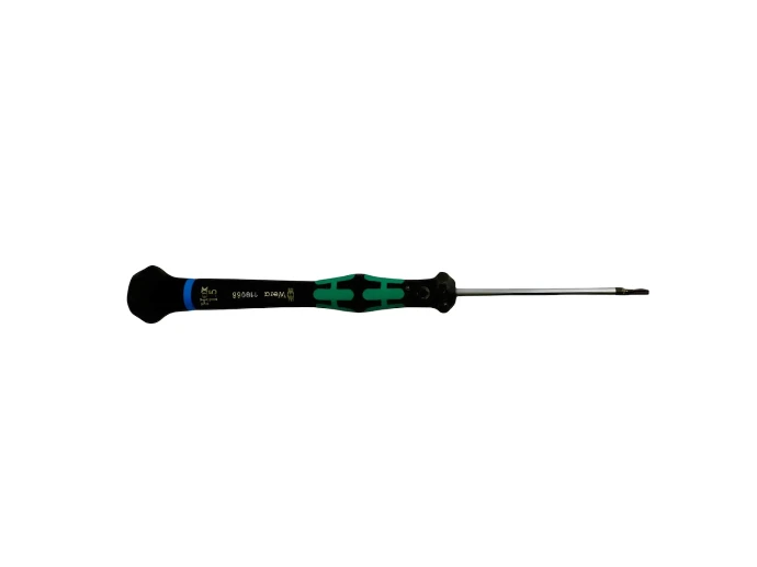
Wera 1.5mm Hex+ driver ideal for building Turnabot combat robots. Precision fit reduces cam-out and stripped screws for reliable, frustration-free assembly. These drivers are fantastic! They can often drive or remove screws that have stripped with other drivers.
Choosing the right screwdriver helps you assemble your robot cleanly, avoid damaged hardware, and make repairs quickly between battles.
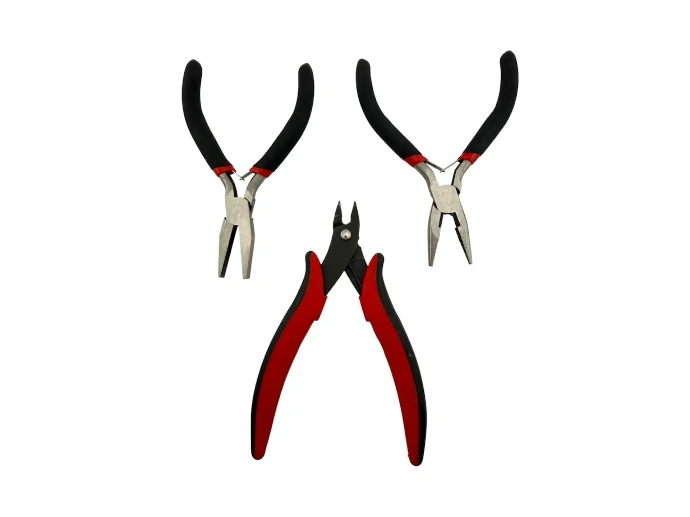
Pliers are essential for gripping, bending, and adjusting small parts inside a combat robot. Flat jaw pliers are useful for holding nuts, straightening metal parts, or applying pressure without damaging components. Needle nose pliers are especially helpful for reaching into tight spaces to grab wires, hold small hardware, or position connectors inside a crowded robot chassis. Flush cutters are designed for cutting wires, zip ties, and small plastic parts cleanly; their flat cutting edge leaves a smooth finish that helps keep wiring neat and prevents sharp edges inside your robot.
When working with small combat robot electronics, a quality temperature-controlled soldering iron or soldering station makes soldering much easier and safer. Fine electronics such as receivers, ESCs, and boards like the Malenki have small solder pads that require precise heat control. A temperature-controlled station allows you to set the correct temperature so solder flows well without overheating or damaging sensitive components.
Choose an iron that supports fine, interchangeable tips, especially needle tips designed for detailed electronics work. These tips allow you to place solder accurately on tiny pads and connectors.
A stable stand, quick heat recovery, and comfortable grip are also helpful features. Good tools make clean solder joints easier to achieve and reduce the risk of accidentally bridging pads or overheating components.
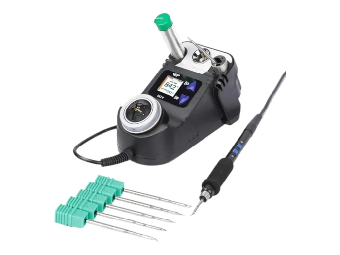
210 Cartridge Soldering Station
Delivers professional-level soldering performance that was once limited to systems costing over $500. Cartridge-style soldering technology allows the heating element to sit extremely close to the tip, giving the user significantly improved control and precision when forming solder joints.
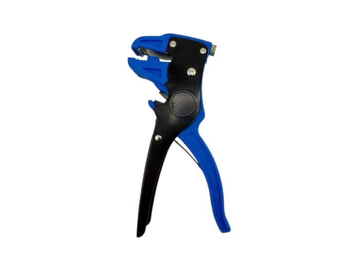
"Quick” or “Auto” strippers. These are so nice to have when stripping a bunch of wires.
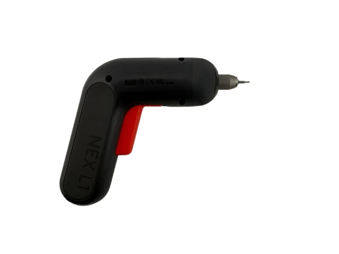
If you're using an electric screwdriver into plastic, go slowly - near 1 revolution per second. Turning the screw too fast can create heat that may soften or melt the plastic, even if the screw doesn’t bottom out.
Component Compatibility
Small combat robots are built from several electronic components that must work together properly. The most important components to match correctly are the batteries, electronic speed controllers (ESCs), motors, radios and receivers. All of these parts must be compatible in voltage, signal type, and current capability.
- Most Turnabot systems use 2-cell LiPo batteries (2S), which provide about 7.4–8.4 volts. When selecting motors and ESCs, make sure they are rated to operate safely within this voltage range. Using a battery that exceeds the rated voltage of your ESC or motor can damage the component.
- Your ESC must also be appropriate for the type of motor you are using. Brushed motors require brushed ESCs, while brushless motors require brushless ESCs. These systems are not interchangeable.
- The radio and receiver must use the same radio protocol. Most Turnabot kits include the Malenki control boards which utilize the AFHDS 2A radio protocol. You must ensure that your radio also uses the AFHDS 2A protocol (the "2A" on the end is important).
- Finally, consider current capacity. Your ESC should be able to safely handle the current drawn by the motor under load. Choosing an ESC with sufficient current capability helps prevent overheating and improves reliability during matches. Ideally your ESCs will have Over Current Protection (OCP) that is high enough to exceed the traction available and low enough to protect themselves and the motors.
Checking compatibility before wiring your robot will help prevent damaged electronics and ensure your robot performs reliably in the arena.
How to Find Models
Many builders in the combat robotics community share their robot designs online, making it easy to download, 3D print, and experiment with proven bots or use them as a starting point for your own creations.
How to Design a Combat Robot
Designing your own combat robot is one of the most exciting parts of the builder’s journey. Thoughtful planning and a good design process can help you create a robot that is durable, effective, and easier to build and repair.
When designing a bot, consider the following:
Before designing your robot, carefully review the rulebook for the competition you plan to enter. Arena details can significantly affect your design decisions—such as whether the floor is steel or wood, whether the arena includes pits or Out Of The Arena (OOTA) zones, and what hazards or boundaries are present. The rules may also restrict certain materials, weapons, or overall dimensions. Some competitions include special allowances such as weight bonuses for multi-bots or non-conventional drive systems. Understanding these details early helps ensure your robot is legal, competitive, and designed specifically for the arena it will fight in.
Decide what style of robot you want to build (flipper, launcher, vertical grabber, horizontal grabber, lifter, wedge, spinner, etc.) and how the weapon will interact with opponents. Your weapon choice will influence nearly every part of the robot’s design, including weight distribution, durability, and how you plan to control or disable other robots.
Every weapon type has a drive system that complements it. Some robots benefit from very high speed, others from strong pushing power, and others from precise control and maneuverability. With practice, most drivers can learn to control a robot that is faster than they were initially comfortable with. However, many matches are still lost due to driving errors, so a drive system that is powerful, controllable, and practiced often leads to more consistent results.
Carefully consider every possible position your robot could end up in during a match. Avoid any configuration where the robot can become balanced in a way that prevents the wheels from touching the ground, since most matches end when a robot is unable to move. Even in situations such as being pushed against a wall or landing at an awkward angle, the design should ensure the wheels can regain contact with the floor or that the Self-Righting Mechanism (SRiMech) has enough range and strength to recover. Avoiding large flat surfaces and ensuring there is enough mass and power in the weapon or wheels to “rock” the bot by accelerating and decelerating can also help prevent situations where the robot becomes stuck.
Winning the ground game is often the primary factor in winning a match. If you consistently get underneath your opponent, you control the interaction and they are unlikely to be able to hit you effectively. Features such as wedges, forks, and low leading edges help your robot reach under an opponent’s armor, lift their wheels, and control positioning in the arena.
Designing a strong ground game often involves tradeoffs—staying compact versus extending long, low wedges, or placing weight on the front edges versus keeping enough weight on the drive tires for traction. Careful balance between these competing factors is key to building a robot that can both win the first engagement and maintain control.
Every part contributes to the robot’s total weight, so plan carefully to stay below the class limit. Any spreadsheet program works well for tracking parts and weights. Start with the components you must have—battery, motors, control board, wiring, servo, etc.—and include the weight of screws, nuts, and connectors early in your estimate since hardware adds up quickly. Then see how much weight you have left for the chassis, armor, wheels, tires, and weapon system.
Think about how your robot will handle impacts. Even in “open air safe” competitions the collisions can be significant. In full combat competitions, be sure to consider all weapon types—vertical spinners, horizontal spinners, undercutters, and overhead hammer-saws. Plan for your armor to absorb several hits with little or no functional damage, and think about how impact forces will travel through the robot so critical components like batteries and electronics remain protected. It’s also wise to design armor and exposed parts so they can be replaced quickly if they do take damage.
Design the robot so batteries, motors, and electronics can be accessed and repaired easily between matches. Battery swaps should be quick, and critical components should not require disassembling the entire robot to reach them. Use connectors where possible and avoid burying parts under multiple layers so repairs can be made quickly in the pit.
Combat robots are built from a wide range of materials, even in the smallest weight classes. Builders may use combinations of carbon fiber, aluminum, titanium, different hardnesses of steel, UHMW, plastics with varying stiffness, and tires with different levels of softness depending on the job each part must perform. At the same time, some very successful robots are built almost entirely from a single material. The key is choosing materials that provide the right balance of strength, weight, flexibility, and durability for the specific role each part plays in the design.
Consider how each part of your robot will be made. Parts may be hand-made, 3D printed, laser cut, machined, or purchased off-the-shelf. The manufacturing method you choose can affect the cost, strength, weight, and how quickly you can repair or replace parts during competition.
Many builders design their robots using CAD software such as Fusion 360, Onshape, SolidWorks, or Tinkercad, which allows you to test fit parts before printing or machining them.
Resources:
- Foxic CAD-A-Long (Fusion 360)
- HLModTech (TinkerCAD)
- EmanMade (SolidWorks)
All successful combat robots go through multiple design iterations. Builders design, build, test, learn from what works and what fails, and then improve the robot in the next version. Expect to repeat this cycle several times as you refine the design and discover ways to make the robot stronger, more reliable, and more effective in the arena.
3D Printing Tips
3D printing is one of the fastest ways to prototype and manufacture parts for small combat robots. Many chassis, weapon systems, mounts, and armor pieces can be printed quickly and replaced between matches if they break.
At Turnabot, we currently print most parts using Bambu Lab X1 Carbon (X1C) printers. They provide excellent reliability, strong layer adhesion, and fast print speeds, which are especially helpful when iterating designs and mass producing a wide variety of robot parts.
Materials we commonly use:
Duramic PLA+ – This is our primary material for most structural parts such as chassis, arms, mounts, and brackets. PLA+ prints easily, produces strong parts, and is a great balance of durability and stiffness.
Priline 98A TPU – We often use TPU for plows, weapons, and flexible armor. The stiff Priline TPU absorbs impacts extremely well, while retaining sufficient stiffness to make large functional parts.
Helpful printing tips for builders:
Wall count is more significant than infill – Wall count generally impacts both strength and weight quite a bit more than infill. 150g bots often run as low as 2 walls and 15% infill in some areas. 1lb Plastic Ants often run 4–6 walls (or more) to produce stronger parts versus relying on infills over 30%. (Some parts are printed solid, in those cases often being all walls is superior to 100% infill. Testing is really the best way to determine the ideal print settings.)
Orient parts for strength – Layer lines are usually the weakest direction, so orient parts so the layers run perpendicular to the forces the part will experience. In many cases the print orientation can increase (or decrease) strength by 2-4 times!
Use chamfers and fillets – Rounded edges, particularly interior corners, reduce stress points and help prevent cracks during impacts.
Avoid thin sections – Very thin printed parts can fail quickly in combat. Extra thickness often adds durability without much weight penalty.
Test and iterate – One of the biggest advantages of 3D printing is how quickly you can improve a design. Print, test, adjust, and print again.
With good design choices and thoughtful print settings, 3D printed parts can be surprisingly durable and are a great way to experiment with new robot ideas quickly.
Wiring Basics
Proper wiring is essential for reliable robot performance. Clean wiring helps prevent electrical problems, makes troubleshooting easier, and reduces the risk of damage during matches. Take time to plan your wire routing, where wires will be secured, and where slack is needed (generally called "strain relief") so connections are not stressed during impacts or movement.
General wiring tips:
Keep wires short but not tight. Leave a little slack so wires are not pulled when parts move or when the robot takes an impact.
Secure wires and connectors. Use zip ties or clips to keep wires from getting caught in moving parts like wheels or weapons.
Use proper polarity. Always double-check positive (+) and negative (–) connections before powering the robot. Reversed polarity can permanently damage electronics.
Insulate exposed connections. Use heat shrink tubing or electrical tape to prevent shorts.
Taking a few extra minutes to wire your robot carefully will make your system more reliable and easier to repair when it’s time to get back into the arena.
The Malenki acts as the robot’s receiver, drive controller, and sends Pulse Width Modulation (PWM) signals to Brushless ESCs that tell the motor how fast and in what direction to spin. (The Malenki can connect to 2 total PWM devices; Brushless ESCs, servos, or one of each)
Connect ESC power and ground wires
The ESC receives full battery power through the Malenki’s dual power rings, which act as the robot’s main power distribution points.
Connect the ESC positive power lead to the + power ring on the Malenki.
Connect the ESC ground lead to the – power ring on the Malenki.
Connect the ESC signal wire
- The ESC has a control cable with a signal wire (usually white, yellow, or orange).Solder this signal wire to the WEAPON3 PWM pad on the Malenki.
Connect the motor to the ESC
Brushless motors have three wires that connect to the ESC. The initial order does not matter.
Check motor direction
Safely and slowly test the weapon control. If the motor spins the wrong direction, swap any two of the three motor wires between the ESC and the motor.
Servos are commonly used for mechanisms such as grabbers, lifters, or weapon linkages. The Malenki acts as the robot’s receiver, drive controller, and sends Pulse Width Modulation (PWM) signals to servos that tell the servo how fast and in what direction to move. (The Malenki can connect to 2 total PWM devices; Brushless ESCs, servos, or one of each)
Connect servo connector power and ground wires
The servo receives full battery power through the Malenki’s dual power rings, which act as the robot’s main power distribution points.
Connect the servo positive power lead to the + power ring on the Malenki.
Connect the servo ground lead to the – power ring on the Malenki.
Connect the servo signal wire
- The servo has a control cable with a signal wire (usually white, yellow, or orange).Solder this signal wire to the WEAPON3 PWM pad on the Malenki.
Soldering
If you’re new to soldering or need a refresher, we strongly recommend starting with the course "How to Build a Wiring Harness from Scratch" in Turnabot Tech Training. In the course, you’ll learn step-by-step how to build a proper wiring harness, including how to cut wires to length, strip and twist wires, tin connections, and create strong, reliable solder joints.
Once you understand the basics, the following tips can help improve your soldering results:
A temperature-controlled soldering station helps produce clean joints without damaging components. For most electronics work, a temperature around 350–380°C (660–720°F) works well.
The Temperature Behavior Test (More Important Than the Number that the iron says)
Right temperature:
Solder melts almost instantly (within 1–2 seconds of touching the hot joint).
Flows smoothly and forms a shiny coat.
Joint heats quickly, but insulation on nearby wires doesn’t melt or burn.
Too cool:
Solder sits like a ball on the surface.
You have to hold the iron on the joint for a long time.
Joint looks dull, grainy, or cracked = “cold solder joint.”
Too hot:
Smoke beyond normal flux vapor.
Pads lift off the board or plastic insulation shrinks back fast.
Quick Tip Test
Touch solder to the iron tip only: it should melt immediately but not burn off like water on a skillet.
Then touch the iron tip to the metal you’re soldering: if it takes more than 2–3 seconds to melt solder on the workpiece, you’re probably too cool or need better tip contact.
Before joining wires or attaching them to pads, apply a small amount of solder to the exposed wire. This is called tinning and helps the solder flow more smoothly when making the final connection.
Benefits of Tinning
Stronger Bonds – Pre-coats the wire and motor tabs, so solder flows together quickly for a solid connection.
Better Conductivity – Lowers electrical resistance, keeping motors cooler and more efficient.
Thermal Protection – Splits the heating between tinning and final joining, so wires and motor tabs aren’t overheated.
Increased Longevity – Reduces stress on solder joints, preventing cracks and failures over time.
Tips for Success
Keep your iron tip clean and shiny for best heat transfer.
Apply solder to the heated part, not just the iron tip.
Use just enough solder—shiny and smooth, not blobby.
Practice tinning on scrap wire before working on your bot.
By mastering tinning, you’ll create joints that are stronger, safer, and more reliable in competition.
Touch the iron to the metal parts you are joining first, then feed solder to the heated joint. This allows the solder to flow properly and bond to the surfaces.
Using the correct amount of solder is key to creating strong, reliable connections.
A good solder joint should be smooth, shiny, and properly filled, not a large blob or a dry, uneven connection. For solder rings or through-holes, the joint should be completely filled with solder so no ring is visible, ensuring a solid mechanical and electrical connection.
When soldering stranded wire, apply enough solder that the strands are fully wetted and nearly indistinguishable, but not so much that the wire becomes overly stiff. Too much solder can cause bridges and shorts, while too little can lead to weak or unreliable joints—aim for complete coverage with clean, controlled application.
Using devices to hold wires and components steady while soldering is called work-holding. Good work-holding is one of the most important—and often overlooked—parts of soldering and assembly. Trying to hold wires, connectors, and a soldering iron at the same time almost always leads to poor joints, burned fingers, or damaged components. Securing your work allows you to focus on making a clean, precise connection.
Use tools like helping hands, small vises, clamps, clay, blu-tak, or even tape to hold parts in place before you start soldering. The goal is to keep everything stable and aligned so nothing moves while the solder is molten. Whenever possible, position parts so they are supported without needing to be held by hand.
For best results, mechanically secure the connection before soldering—for example, by twisting wires together or feeding them through a hole or pad. This ensures the joint stays in place while you apply heat and creates a stronger, more reliable connection.
Taking a moment to properly secure your work will make soldering easier, safer, and much more consistent.
After soldering, cover exposed connections with heat shrink tubing, electrical tape, hot-glue, or some type of insulation whenever possible. This prevents shorts and protects the joint from stress during impacts.
Before powering your robot, inspect every connection. Look for loose wires, cold solder joints, incorrect polarity, drips of solder, and accidental solder bridges between pads.
With a little practice, soldering becomes a fast and reliable way to create strong electrical connections for your combat robot.
Radio Setup
Download these Radio Setup Instructions to make sure your robot drives in the correct direction and your weapon moves the right amount without damaging the servo or mechanism. The guide walks you step-by-step through setting radio endpoints, correcting drive direction, and adjusting channels so your bot drives and actuates properly.
Below are the radio setup instructions for Suplex Slam. For more instructions about specific bots, go to Turnabot Tech Training and find the course for your specific bot.
Radio Setup Instructions for Suplex Slam
Malenki Troubleshooting
The Malenki is the central control board for many small combat robots, acting as both the receiver and motor controller interface. If your robot is not responding correctly, a few quick checks can often identify the problem.
- Verify that the positive lead from the battery goes to the switch.
- Verify that the positive lead from the switch goes to the "+ +" solder rings.
Verify that the negative lead from the battery goes to the "- -" solder rings.
Verify that there are no stray strands of wire on ANY of the connections to the Malenki.
Verify that there are no drips of solder anywhere on the Malenki.
Verify that there are no solder bridges between connections.
Verify again that the polarity is correct all the way from the battery to the Malenki.
- Are there any LEDs illuminated on the Malenki? If the red or blue LED is illuminated then the Malenki has power.
Check the battery voltage at the Malenki. A 2S battery should always only be between 6.8 and 8.4 volts. Ideally it should be between 7.4 and 8.4 volts. If there is not voltage between 6.8 and 8.4 volts at the Malenki then check the battery itself.
If the battery has correct voltage then check the voltage at the Malenki wire on the switch.
Check that the battery connector is firmly seated and that no wires have pulled loose.
Inspect solder joints at the switch and at the Malenki and wiring for broken connections or reversed polarity.
If you have correct voltage at the Malenki and neither LED is illuminated then take clear, high-resolution photos of the Malenki from at least two angles on each side (minimum of four photos total), along with at least one photo of the complete wiring harness. Send those as well as a detailed description of the problem and all troubleshooting steps that have already been attempted to builder@turnabot.com
Mode | Red LED | Blue LED | Status |
Bind mode | Solid | Flashing | Ready to bind to a radio with AFHDS 2A protocol (the 2A at the end is important). When you first power on a new Malenki it should be in bind mode. |
Configuration mode | Solid | Flickering | Connected to the radio. Any time the Malenki is powered on for 5 seconds or more before it connects with a radio, once it does connect it will be in Configuration Mode. This includes if a new Malenki is powered for 5+ seconds before binding. Moving the drive stick will put the Malenki into Drive Mode. |
Drive mode | Solid | Solid | Ready to battle. |
Bound but not connected | Solid | Off | Bound to a radio but not currently receiving a signal from that radio. After 90 seconds in this state the Malenki will automatically go back into Bind mode. |
Replace | Flashing slowly | Off | No internal signal is being received from the radio module to the processor. This is typically caused by electrical damage to the radio chip, which can result from a voltage spike or, in some cases, a strong static discharge. |
If both the red and blue LEDs are solidly illuminated and the bot does not move:
- Verify that the drive motors turn easily by hand and their electrical connections are secure.
- Make sure the battery is fully charged and properly connected.
Check that the battery connector is firmly seated and that no wires have pulled loose.
Inspect solder joints and wiring for broken connections or reversed polarity.
- How do I stop it from entering bind mode? Bind mode is entered automatically after a delay if no signal is received. To prevent automatic bind mode, just turn on the bound transmitter during the first minute after power on - if you don’t want to drive, just turn it off again and the Malenki will not re-enter bind mode.
If you are sure that all of the connections are correct but you are still having trouble follow these steps in order:
- If possible, factory reset the Malenki by sending 7 high-low pulses on Channel 5 while in Configuration mode.
- If possible, bind the Malenki to a different radio.
- Factory reset the radio.
- After having factory reset the radio, factory reset the Malenki again.
- Take clear, high-resolution photos of the Malenki from at least two angles on each side (minimum of four photos total), along with at least one photo of the complete wiring harness. Send those as well as a detailed description of the problem and all troubleshooting steps that have already been attempted to builder@turnabot.com
Competition
Take your robot from the workbench to the arena.
Ready to battle? This section explains how competitions work, how to prepare for your first event, what to bring, and how to improve your robot after each fight. Learn how builders move from beginner bots to competitive machines.
Take Your Bot to the Next Level
Ready to take your bot to the next level? Small improvements—like winning the ground game, increasing tire grip, and printing flexible TPU parts—can make a huge difference in how your robot performs in the arena.
You can attach the acetate using super glue, hot glue, or 3M VHB (very high bond) tape.
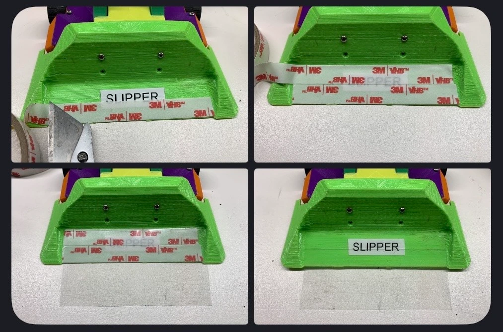
Arena floors are often dirty, dusty, and covered in debris, which can significantly reduce traction. One of the most effective ways to improve grip is to clean your tires immediately before each match. A common method is to use a strip of duct tape placed sticky-side up on the table and roll the tires across it as the final step before a fight. This removes dust and debris, helping your robot maintain better traction and control in the arena.
How Do Competitions Work?
Combat robot competitions bring builders together to test their designs in a controlled arena. While specific rules vary by event and weight class, most competitions follow a similar structure designed to keep matches exciting while keeping the participants and audience safe.
Robots compete in different weight classes, and every robot must meet the maximum weight limit for its class. Robots are weighed before competing to make sure they follow the rules.
Fairyweight (150g / ~0.33 lb)
The tiniest combat robots—fast to build, lower-cost, and easier to transport. This class is great for everyone from beginners to the most experienced. Usually fought in smaller arenas with lighter impacts.
Spiderweight (0.5 lb / 226g) (up-and-coming class!)
A newer, growing class that’s bigger and tougher than Fairyweights but still lightweight and affordable to compete with. Bonus 1: In many competitions, two Spiderweights can team up as a multibot in the Antweight division (as long as the combined weight meets the event’s multibot rules). Bonus 2: The internal components are very common in both 150g and 1lb bots so you can easily build a bot in either of those classes.
Antweight (1 lb / 454g)
One of the most popular “starter serious” classes—big enough for real weapons and durable designs, but still manageable for newer builders. Rules vary by event, so always check what weapon types and materials are allowed.
PLANT (Plastic Antweight) (1 lb / 454g)
A special type of Antweight where bots must be built mostly from plastic/approved materials (event rules decide the exact limits). It’s designed to keep the class more affordable, encourage low-cost and impressive destruction, and make repairs less painful.
Beetleweight (3 lb / 1.36 kg)
A major step up in size and power—more space for stronger drive systems, thicker armor, and harder-hitting weapons. It’s super exciting to watch, but it’s typically more expensive and demanding to build safely and reliably.
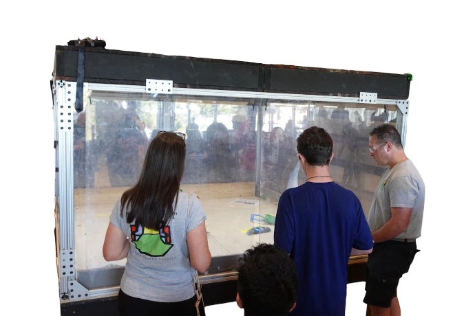
The vast majority of matches take place inside protective arenas with strong walls and a clear viewing area. The arenas keeps the robots contained while allowing spectators to safely watch the action. There are growing opportunities to compete in "open-air safe" competitions that use lightweight arenas with pits.
A typical match lasts 2–3 minutes. During this time, two robots fight while drivers control them using radio transmitters. The goal is to disable, control, or outlast the opponent.
A match can end in several ways:
Knockout (KO): One robot becomes unable to move or continue fighting.
Tap-out or surrender: A driver may stop the match if their robot is badly damaged.
Judge’s decision: If both robots survive the full time limit, judges determine the winner.
Judges typically score matches based on three main factors:
Damage – Which robot caused more visible or functional damage to the opponent
Control – Which robot showed better driving and positioning
Aggression – Which robot actively pursued and attacked the opponent
Competitions have strict safety requirements. Robots must have removable safety links or power switches, proper battery protection, and must pass inspection before entering the arena. Each event may also have additional safety rules, so be sure to review the rulebook for the specific competition you are attending.
Combat robotics competitions are a great way to test your design skills, learn from other builders, and see how your robot performs under real battle conditions. Every match is a chance to improve your design and strategy for the next fight.
Prepping for Your First Event
Your first combat robotics event is exciting, and a little preparation goes a long way toward making the experience smooth and fun. The more ready your robot and tools are before you arrive, the more time you’ll have to focus on driving, learning, and battling.
- Test your robot thoroughly.
- Before the event, make sure your robot drives reliably, the weapon works consistently, and your radio is properly bound and configured. Test it multiple times so you know everything functions the way you expect.
- Bring spare parts.
- Combat robots often take damage, especially in later matches. It’s helpful to bring extra wheels, printed parts, fasteners, and wiring so you can repair your robot between fights.
- Pack the right tools.
- Bring the tools you used to build the robot, such as screwdrivers, hex drivers, pliers, soldering tools, flush cutters, and spare zip ties. If you needed a tool during the build, you’ll probably need it at the event.
- Bring extra batteries.
- Matches happen quickly, and you may need to fight multiple rounds in a short period of time. Having fully charged spare batteries ensures your robot is always ready for the next match.
- Label your equipment.
- Events can get busy, and many builders have similar tools and parts. Labeling your robot, batteries, chargers, and tools helps prevent mix-ups.
- Review the event rules.
- Each competition may have slightly different requirements. Check the event’s rules, safety requirements, and inspection checklist ahead of time so there are no surprises when you arrive.
- Plan for quick repairs.
- Between matches you may only have a few minutes to fix your robot. Designing your robot so important parts are easy to access and replace can make a huge difference during competition.
Most importantly, remember that your first event is about learning and having fun. Every builder improves their robot through experience, and each match teaches you something new about design, driving, and strategy.
What Do I Bring to Competition?
Download the competition checklist so that you don't forget anything on your big day!
Turnabot Combat Robot Competition Checklist
How Do I Improve Now?
After your first competition, one of the best ways to improve is simply to drive and battle often. Building or modifying a durable, non-destructive bot lets you practice regularly with friends, experiment with new ideas, and develop your driving skills without constantly repairing major damage.
Builder Resources
Learning resources and communities for builders.
Explore useful links for continuing your robotics journey. Find the Turnabot 3D CAD library, eLearning courses, design tools, community groups, and other resources that help builders learn faster and create better robots.
Combat Robot Resources
Discord Servers with Great Communities
CAD Resources:
- Foxic CAD-A-Long (Fusion 360)
- HLModTech (TinkerCAD)
- EmanMade (SolidWorks)